

Cambridge, UK
invalid location provided
Compiled by Jim Haseloff at the University of Cambridge.
This site contains details of recent papers and activity in Synthetic Biology, with particular emphasis on: (i) development of standards in biology and DNA parts, (ii) microbial and (iii) plant systems, (iv) hardware for scientific computing and instrumentation, (v) tools for scientific productivity and (vi) collected miscellany.
The site also contains details of Synthetic Biology research and teaching at the University of Cambridge, including the annual iGEM team run by Jim Ajioka, Jim Haseloff and Gos Micklem in Cambridge.
ICBE brings together researchers who are using quantitative approaches to advance the understanding and application of molecular biology. These scientists, engineers, and professionals...
The global bioeconomy is gaining pace and the UK is positioning itself at the forefront. Illustrating the progress made in exploiting industrial biotechnology in the UK, the Industrial...
Technology is driving revolutionary changes in biology. Over the past decade, scientists and engineers have begun to define the path forward in the genomic era. Systems Biology has arisen...
Now that we know the sequences of many genomes, from a wide variety of organisms and even from individuals with unique characteristics, many researchers have turned to making intentional...
The developments within synthetic biology promise to change the world in significant ways. Yet synthetic biology is largely unrecognized within conservation. The purpose of the meeting...
(Re-)constructing and Re-programming Life This conference will provide an in-depth discussion forum among practitioners of the various fields underlying Synthetic Biology. It aims to...
The BioBricks Foundation is pleased to announce The BioBricks Foundation Synthetic Biology 6.0 Conference (SB6.0), which will take place on July 9-11, 2013 at Imperial College, London,...
This course will focus on how the complexity of biological systems, combined with traditional engineering approaches, results in the emergence of new design principles for synthetic...
from: http://www.martijnthe.nl/
In this tutorial I'll describe how you can connect the optical sensor inside a cheap mouse to your Arduino and have it read out the x- and y-movements. This will enable your Arduino to handle mouse input, detect surface movements, measure surface speed, etc.
This is what you need:
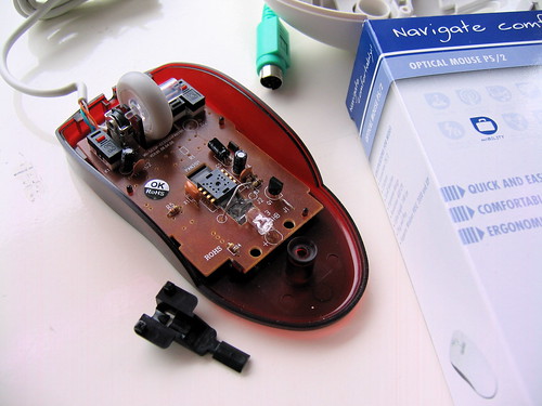
The optical sensor and LED were covered with the black protective cap. Take it off carefully.
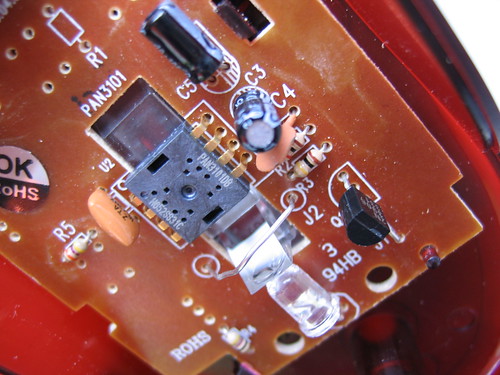
Check out the datasheet of the sensor you're dealing with (Google).We only need to connect 4 pins of the sensor to the Arduino, of which two are used for data and two for the power supply. The sensor uses bi-directional serial communcation over one data line (SDIO, pin 3). The second data pin (SCLK, pin 4) is used to time the bits. In case of a different type of sensor, the pin numbers might be different.

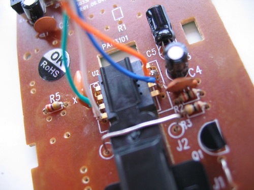
To make sure the mouse's own controller does not interfere with the Arduino, I had cut the SDIO and SCLK wires running to the chip in the mouse. I'm not sure whether this is really necessary, so you might try first without cutting them.
Solder wires to the four legs of the sensor that I indicated above. The +5V should go to the 5V Power pin on the Arduino, the GND should go to the GND Power pin on the Arduino. Pretty straightforward. Connect the SCLK to Arduino digital pin 2 and SDIO to Arduino digital pin 3. (You are free to use other pins as well, but in this tutorial I'm using pin 2 and 3.)
Download this .zip package with the library and example sketches. Expand the archive and move it into:
arduino-0010/hardware/libraries/
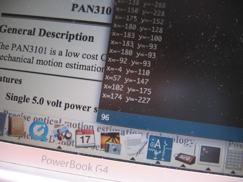
Restart the Arduino IDE. The examples should appear in File > Sketchbook > Examples > Library-OptiMouse. Open the Coordinates example and upload it to your Arduino board. Start Arduino's serial monitor (38400 baud) to see the coordinates of your mouse coming in... Done!
2008-11-18 : Added some support for the ADNS-2083
2009-01-30 : Fixed compatibility issue with Arduino 0012 (Thanks Mark for notifying me.)
This tutorial is based on Benoît Rousseau's example on the Arduino Forum. I just wrapped his functions inside a library. If you have suggestions for improvements of this tutorial or the library, feel free to mail me: post [at] martijnthe [dot] nl.
PhD Studies in Cambridge
The Board of Graduate Studies manages admission of the University's graduate students. Prospective students should start here - for an introduction to the University of Cambridge, the courses we offer, how to apply for postgraduate study, how your application will be processed, and immigration and other important information.
Click here for more information about Cambridge
